Rancakmedia.com – Berikut ini adalah penjelasan mengenai fungsi flowchart dalam pemrograman yang mungkin saja belum kamu ketahui. Sekelompok pengembang sedang mengadakan rapat internal, dan salah satu dari mereka memiliki diagram yang diproyeksikan ke dinding.
Klien yang tertarik untuk membeli program tim ditunjukkan diagram tersebut. Investor terkadang diperlihatkan grafik ketika mereka mencoba memutuskan di mana harus menaruh uang. Flowchart adalah istilah untuk jenis grafik ini.
Ide dasarnya agak mudah, meskipun tampak rumit dan berantakan. Bahkan, kemudahan penggunaan adalah tujuan utamanya. Keseluruhan proses kreatif dapat dirangkum dengan dua kata: visualisasi alur kerja dan kesederhanaan.
Saat membuat aplikasi atau situs web, diagram alur berguna di seluruh fase program dan pemasaran. Pengembang membuatnya sebagai cetak biru awal untuk alur logika program.
Sebagai bagian dari paket penawaran, tim pemasaran membutuhkannya untuk menguraikan parameter program dengan jelas.
Pengertian Flowchart
Untuk menunjukkan bagaimana sebuah program beroperasi, pengembang menggunakan diagram yang disebut flowchart. Ini juga dapat digunakan secara lebih umum untuk mengkarakterisasi operasi sistem.
Diagram alir digunakan secara luas dalam bidang yang menuntut representasi visual yang rumit, termasuk seperti kedokteran, kimia, dan teknik.
Gambar ini sangat berguna di seluruh siklus hidup pengembangan pemrograman, mulai dari ide awal hingga pengujian dan perbaikan masalah.
Karena kompleksitasnya, program komputer saat ini harus divisualisasikan dalam program metodis dan terorganisir untuk mewakili secara memadai bagaimana mereka akan berfungsi.
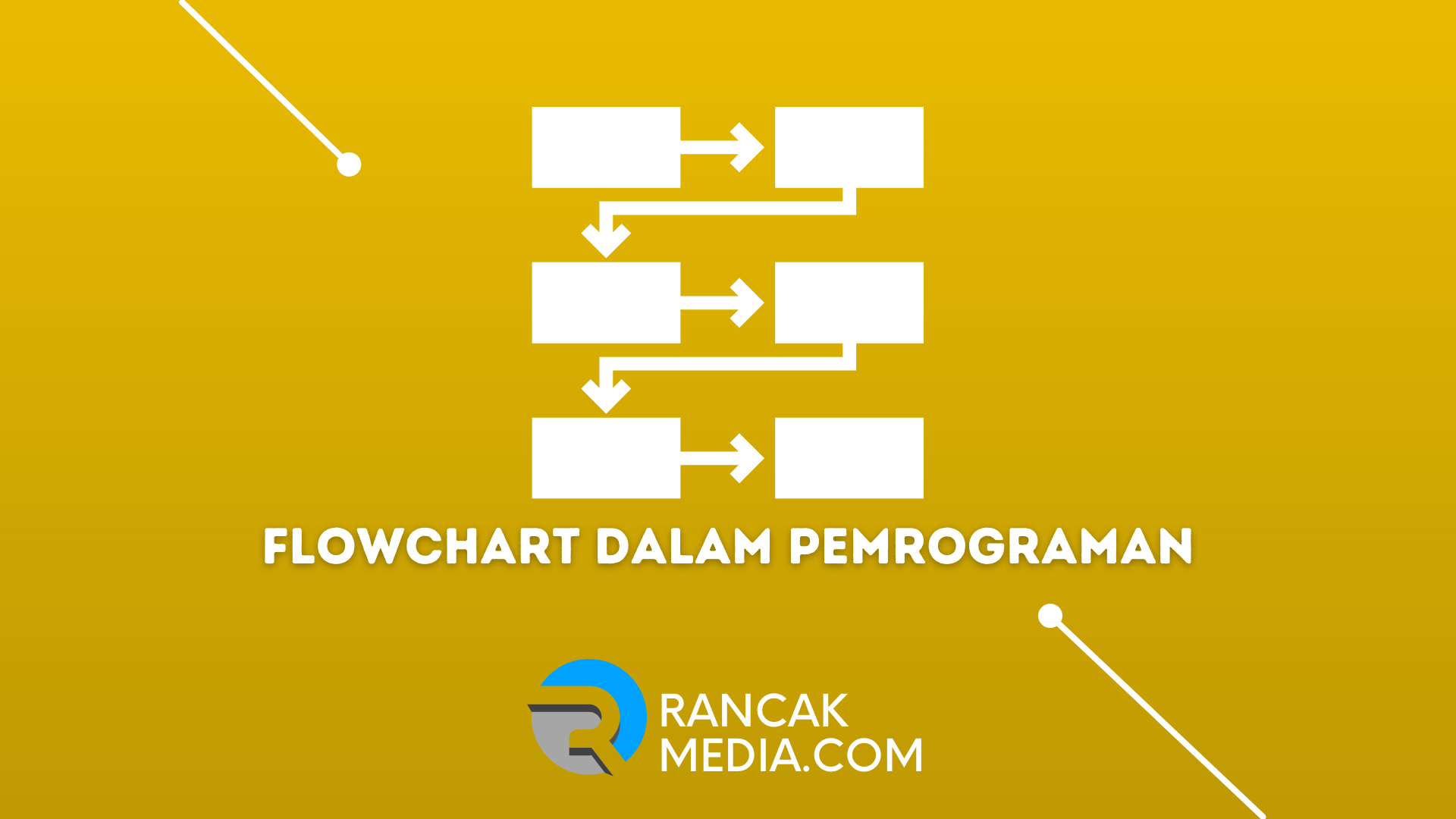
Flowchart adalah representasi grafis dari langkah-langkah yang terlibat dalam eksekusi program komputer, dari input ke pemrosesan hingga output.
Sejarah Flowchart
Tidak ada data yang dapat diandalkan tentang asal-usul metode diagram representasi data. Setidaknya ada beberapa catatan dari masa lalu yang dapat kami lihat.
Pada pertemuan American Society of Mechanical Engineers pada tahun 1921, Frank dan Lillian Gilberth memberikan ceramah berjudul “Process Charts: Langkah Pertama dalam Menemukan Satu Cara Terbaik untuk Melakukan Pekerjaan” (ASME).
Pada Konferensi Penyederhanaan Pekerjaan 1930 di New York, Allan H. Mogensen menginstruksikan sekelompok orang tentang cara memanfaatkan diagram alur untuk tujuan merampingkan proses.
Simbol Gilbert diadopsi oleh ASME pada tahun 1947 sebagai bagian dari “Standar ASME: Bagan Proses Operasi dan Aliran.”
Pada tahun 1949, representasi visual dari alur kerja menjadi norma di bidang desain algoritma dan pemrograman komputer.
Flowchart telah ada sejak saat itu dan telah terbukti sangat penting dalam dunia pemrograman komputer.
Manfaat dan Fungsi Flowchart dalam Pemrograman
Flowchart memiliki berbagai aplikasi sebagai alat bantu visual. Kegunaannya tidak terbatas pada satu bidang, melainkan berlaku secara universal di mana saja ada kebutuhan untuk langkah-langkah yang dapat diulang dalam urutan yang sistematis.
Berikut ini adalah beberapa kegunaan yang paling mendasar untuk bagan:
Meningkatkan Pemahaman Prosedur yang Rumit
Program yang kompleks tentu saja memiliki kurva pembelajaran yang curam. Terlebih lagi jika kamu harus menjelaskannya kepada klien yang tidak terlalu paham tentang seluk beluk pemrograman komputer. Pada titik ini, akan sangat membantu jika kamu merujuk pada diagram.
Grafik yang sederhana dan terorganisir dengan baik dapat membuat materi pelajaran yang paling rumit sekalipun mudah dipahami. Memahaminya juga tidak sesulit membaca deskripsi tertulis yang lengkap. Klien juga lebih terbuka terhadap alasan yang kamu berikan.
Meningkatkan Produktivitas dan Membuat Debugging
Flowchart adalah evaluator. Kamu dapat menggunakannya untuk memeriksa proses program kamu. Masih ada waktu untuk memperbaiki program kamu dengan menghilangkan langkah-langkah yang tidak perlu atau mengubah rute data.
Proses memperbaiki bug dikenal sebagai “debugging” dalam dunia pemrograman komputer. Menemukan dan memperbaiki kesalahan dan hambatan kinerja dalam program adalah apa yang dimaksud dengan ini.
Memiliki representasi visual dari aliran sistem saat debugging sangat meningkatkan kejelasan dan efisiensi. Inilah yang dilakukan bagan untuk kami ketika kami perlu mengevaluasi atau memperbaiki sesuatu:
- Alat untuk mengidentifikasi proses ekstra dan menghilangkannya.
- Memfasilitasi pemeriksaan penyimpanan dan transmisi data yang tidak terpakai.
- Memfasilitasi interaksi dengan menyediakan media visual untuk informasi yang tepat dan lengkap.
- Sebuah batu loncatan untuk menjelajahi wilayah intelektual yang belum dipetakan.
- Konten harus disertakan dalam paket proposal yang dikirim ke calon pelanggan dan pemodal.
Kegunaan flowchart yang meluas menjelaskan mengapa mereka begitu penting dalam dunia pemrograman komputer.
Simbol Flowchart
Kumpulan ikon standar disepakati oleh semua pihak untuk menggambarkan aliran proses secara paling efektif. Pada tahun 1960, American National Standard Institute (ANSI) secara resmi menetapkan seperangkat simbol standar.
Organisasi Internasional untuk Standardisasi (ISO) secara resmi menerima kumpulan simbol ANSI sepuluh tahun kemudian (ISO).
Dalam penggunaan aktual, setiap simbol memiliki tujuannya sendiri dan harus ditempatkan dengan benar. Penjelasan rinci tentang cara kerja perangkat lunak tidak lagi diperlukan oleh programmer. Audiens akan memahami prosesnya hanya dengan melihat diagram alir.
Flowchart meningkatkan kolaborasi ketika semua orang menggunakan simbol yang sama. Tanpa penjelasan yang rinci, audiens dapat langsung memahami arti penting dari setiap simbol. Cukup jelaskan proses apa yang terjadi di dalam simbol.
| Nama | Arti |
|---|---|
| Start / Stop | Menandai awal dan akhir aliran |
| Process | Matematika dan manipulasi data |
| Input / Output | Input yang dibuat oleh pengguna dan output dari pemrosesan |
| Decision Making | Membuat pilihan di antara banyak tindakan potensial |
| Arrow / Flow | Menunjukkan alur yang diambil oleh makna saat bergerak dari satu simbol ke simbol lainnya |
| On-page Connector | Dengan menghubungkan garis alir bersama pada lembar yang sama |
| Off-page Connector | Mengintegrasikan proses dari banyak lembar kerja |
Jenis-Jenis Flowchart
Jika kamu memecahnya berdasarkan tujuan yang dimaksudkan, kamu akan menemukan bahwa sebenarnya ada banyak kategori yang berbeda.
Process
Ini berfungsi sebagian besar sebagai kerangka kerja teoritis untuk membuat perangkat lunak baru. Diagram semacam ini berguna untuk programmer dan desainer saat mereka melakukan pekerjaan awal. Hasil akhirnya harus berupa proses pembuatan yang efisien dan efektif.
Elemen utama dari desain program asli bahkan termasuk diagram Proses. Semua yang terlibat dapat menggunakan diagram ini sebagai panduan saat mereka fokus pada tanggung jawab spesifik mereka.
Dengan adanya proses yang ditetapkan, semua orang dalam tim dapat bekerja menuju hasil akhir yang sama.
Swimline
Membuat diagram alur proses adalah penggunaan yang lebih khusus untuk gaya diagram ini. Diagram Swimlane mencakup berbagai macam tugas yang mungkin, seperti berikut ini:
- Business Process Management (BPM)
- Enterprise Resource Planning (ERP)
- Company Sale (penjualan)
- Kebijakan dan Perizinan
- Komunikasi dengan customer
Ada beberapa hasil positif dari penggunaan Swimlane untuk memproses proses.
- Fleksibilitas: Anggota staf baru dapat dengan mudah masuk ke dalam rutinitas yang telah ditetapkan.
- Quality: Kepatuhan terhadap swimlane yang telah ditetapkan memastikan standar kualitas yang stabil dan dapat dikelola.
- Visibility: Direktur dan manajemen dapat melihat bagaimana segala sesuatunya berjalan di setiap tingkat operasi.
- Improvement: Memodifikasi keadaan saat ini sehingga lebih produktif dan efisien adalah apa yang kami maksud dengan “perbaikan.”
Workflow
Berguna untuk merujuk pada saat menetapkan protokol, diagram ini mewakili pedoman untuk operasi. Alur kerja berfokus pada dua bidang utama:
- Mengelola Perubahan Melalui Integrasi Proses
- Perspektif SDM tentang Tugas
Untuk mencapai kedua tujuan ini secara bersamaan, sebagian besar Workflow dikembangkan. Tujuan akhir manajemen alur kerja adalah untuk memberikan hasil yang berulang dan berkualitas tinggi dari mengikuti serangkaian praktik yang seragam.
Data Flow
Diagram alir data adalah jenis diagram alir khusus yang digunakan untuk menggambarkan aliran informasi di antara berbagai sistem. Sebuah siklus data, dari input ke penghapusan melalui pemrosesan, penyimpanan, modifikasi, dan penghapusan, secara grafis ditunjukkan di bawah ini.
Ini telah terbukti efektif dalam menjembatani kesenjangan dalam pemahaman antara pengguna akhir dan programmer.
EPC Diagram
Seperti yang kamu lihat, diagram ini memiliki tingkat detail yang tinggi. Untuk lebih spesifiknya, diagram ini unggul dalam menggambarkan proses yang digerakkan oleh peristiwa, yang merupakan proses bisnis komprehensif yang melibatkan setiap area operasi.
Rencana untuk memaksimalkan efisiensi di semua bidang proses disertakan. Bahkan lebih dari jenis diagram lainnya, diagram Event-driven Process Chain (EPC) memiliki simbol-simbol unik mereka sendiri.
Setiap detail dibuat untuk memenuhi persyaratan desainer yang perlu memadatkan proses bisnis yang kompleks ke dalam format visual yang mudah dicerna.
SDL Diagram
Diagram alir yang digunakan untuk menggambarkan program komputer, Specification and Description Language (SDL) banyak digunakan. Untuk menggambarkan sistem secara real time, simbol-simbol yang digunakan konsisten dengan lingkungan bahasa pemrograman.
Tiga bagian utama dari setiap diagram SDL yang diberikan adalah definisi, blok, dan proses. Memecahkan masalah secara internal dan berbicara dengan konsumen adalah dua area di mana SDL bersinar.
Pelanggan lebih cenderung membeli ke dalam sistem yang kamu kembangkan jika fungsinya dapat dijelaskan secara visual.
Process Map
Process Map adalah alat yang sangat berharga bagi siapa saja yang berencana untuk melakukan audit. Process Map mampu mengevaluasi sampai ke variabel terkecil, baik itu dalam ranah perangkat lunak dan elektronik atau dalam kinerja sebuah organisasi.
Langkah-langkah dalam mengembangkan Process Map adalah sebagai berikut:
- Pelajari setiap tahapan proses secara individual.
- Informasi yang dikumpulkan untuk menilai tujuan proses, bahaya, dan kontrol.
- Mewawancarai semua peserta dalam proses dan menggambar Peta Proses.
- Mengidentifikasi hambatan dalam proses dan menerapkan perbaikan.
Dengan menghilangkan detail yang tidak perlu dan berfokus pada hal-hal penting, kamu dapat melakukan audit yang lebih tepat dan menyeluruh.
Process Flow
Meskipun flowchart yang satu ini bukanlah diagram dalam dunia pemrograman komputer, menguasainya akan membuka dunia kemungkinan. Biasanya, para insinyur dan ahli teknologi menggunakan Process Flow.
Cara kerjanya adalah kami hanya menjelaskan proses-proses yang paling penting (mayor) dan meninggalkan proses-proses (minor).
Berikut adalah beberapa contoh penggunaan umum untuk Process Flow:
- Pembuatan Bensin.
- Struktur untuk distribusi gas alam.
- Sumber energi terbarukan, seperti angin dan matahari.
- Hidrologi dan Kontrol.
- Menciptakan Listrik.
- Rekayasa Hidrologi.
Ada juga Alur Proses yang mencakup spesifikasi proses. Diagram Blok dan Diagram Alir Skematik adalah dua nama umum untuk PFD semacam ini.
Tutorial Membuat Flowchart
Jika kamu ingin mendapatkan hasil maksimal dari Flowchart, kamu perlu memastikannya dibuat dengan cara yang benar.
Ada langkah-langkah teknis yang perlu kamu ambil untuk membuat diagram yang mewakili proses dengan benar. Ini adalah tahapan-tahapannya, dalam urutan penampilan:
Tentukan Tujuan
Berbagai jenis diagram dan cara penggunaannya telah dijelaskan di atas. Kamu perlu mengetahui tujuan akhir kamu sebelum kamu dapat melanjutkan ke tahap desain. Kemudian, pilihlah jenis diagram yang benar dan lanjutkan.
Seperti yang kamu lihat, delapan kategori yang disebutkan di atas bukanlah aturan yang keras dan cepat. Kamu dapat menciptakan dengan menyesuaikan atau menggabungkan berbagai jenis grafik yang berbeda.
Ciptakan sendiri untuk memenuhi tujuan spesifik kamu dalam hal memvisualisasikan pekerjaan kamu. Efisiensi komunikasi juga sama pentingnya. Bahkan, jika kamu menambahkan beberapa hiasan pada diagram, pastikan pembeli dapat menangkap pesannya tanpa kesulitan.
Garis Besar
Diagram alur yang mudah diikuti tidak ada. Pertama, proses mendasar dilakukan, dan kemudian prosesnya disempurnakan dengan memasukkan informasi yang lebih halus.
Jangan terjebak dalam seluk-beluk pada titik ini, sebaliknya, cukup buat sketsa proses utama untuk berfungsi sebagai garis besar kasar dari keseluruhan proses yang kamu coba lihat di kepala kamu.
Setelah cetak biru selesai, kamu dapat mengisi bagian yang kosong dengan proses yang lebih spesifik. Alih-alih menghabiskan waktu dan energi untuk mencari tahu secara spesifik di awal, kamu dapat langsung menuju ke solusi yang mudah dan cepat.
Mengisi Hal-Hal yang Spesifik
Tahap ketiga adalah kelanjutan dari tahap kedua. Ketika bentuk dasarnya sudah jelas, kamu bisa mengisinya dengan proses yang lebih spesifik di sepanjang bagian tengahnya atau bercabang ke kedua arah. Ingatlah bahwa skema dilihat secara vertikal, dari atas ke bawah.
Buat ikon pertama di sudut kiri atas untuk mewakili tahap pertama. Ikuti instruksi ke kanan atau ke bawah untuk proses selanjutnya. Langkah selanjutnya adalah memoles diagram kamu dengan menambahkan lebih banyak informasi dalam proses inti.
Jika diperlukan, berikan komentar penjelasan di dalam atau di samping simbol. Jangan membuang-buang ruang pada diagram kamu dengan menulis terlalu banyak detail.
Ingatlah bahwa diagram dimaksudkan untuk membuat proses yang rumit lebih mudah dipahami, jadi jaga agar diagram kamu tetap lugas.
Verifikasi Hasil
Setelah menyelesaikan diagram alur, kamu harus menjalankan beberapa tes untuk memastikan bahwa diagram tersebut secara akurat mewakili diagram.
Kamu dapat menguji efisiensi alur kerja kamu dengan menjalankannya. Lihat bagaimana kinerja program dibandingkan dengan diagram saat dijalankan.
Kamu dapat melihat bagian mana yang tidak bekerja dengan baik dari evaluasi awal. Ubahlah berbagai hal pada saat itu dan coba lagi. Pantau terus bagaimana kinerja sistem setelah upgrade untuk melihat apakah lebih efisien.
Beberapa iterasi dari proses ini mungkin diperlukan. Mungkin perlu waktu bagi perangkat lunak untuk menentukan urutan operasi yang optimal selama uji hasil, terutama untuk aplikasi yang lebih rumit.
Penilaian Kolektif
Hasil terbaik tidak dapat dicapai hanya dengan pengujian hasil. Kamu masih membutuhkan masukan dan analisis dari beberapa sumber. Dapatkan masukan dari tim kamu dengan membicarakan diagram dan meminta ide dari mereka.
Periksa diagram untuk mencari cara-cara di mana efektivitasnya dapat ditingkatkan. Jangan terjebak dalam kebiasaan mengikuti satu prosedur yang telah ditetapkan, sebaliknya, carilah cara untuk meningkatkan proses saat ini.
Jangan sia-siakan kesempatan ini untuk berpikir di luar kotak; inovasi adalah hasil utama yang kamu tuju saat kamu memetakan.
Upaya kelompok akan selalu menghasilkan diagram yang lebih unggul daripada upaya individu.
Terbitkan
Langkah terakhir dalam diagram alur selesai ketika tes hasil dan penilaian kelompok keduanya berhasil. Kamu telah memeriksa fungsinya secara menyeluruh dan mengintegrasikan umpan balik dari semua sumber. Sejauh perencanaan berjalan, seharusnya tidak ada lagi kekosongan.
Bagan kamu kemudian harus dipublikasikan. Buatlah garis dan warna kamu berbeda dan ilustratif. Jangan memberi orang alasan untuk mengalami kesulitan atau salah paham dengan desain akhir kamu. Diagram yang efektif adalah diagram yang dapat dipelajari dan diserap oleh semua orang.
FAQ
Di bawah ini kami telah merangkum beberapa pertanyaan yang sering di tanyakan tentang flowchart, sebagai berikut:
Kapan Kita Menggunakan Flowchart?
Flowchart biasa digunakan baik di dalam melakukan desain maupun mendokumentasikan sebuah algoritma. Sehingga dalam menyusun suatu program langkah pertama yang perlu dilakukan ialah membuat flowchart, yang nantinya akan digunakan sebagai dokumentasi program tersebut.
Kesimpulan
Tujuan flowchart adalah untuk mengekspresikan secara simbolis proses-proses yang terjadi selama eksekusi program, membuatnya menjadi flowchart yang berguna untuk menjelaskan bagaimana sebuah program bekerja.
Flowchart program juga dapat digunakan untuk menjelaskan sistem kepada orang lain. Demikian artikel ini semoga bermanfaat ya.